20+ repeater block diagram
NXP has built a strong position in RF transistors for basestation power amplifiers with reliable and innovative solutions. By combining two pairs.
What Are Your Reviews Of Wifi Boosters Like The Nettec Boost And Signaltech Boost Are They A Scam Quora
In some high power cases 100 Watts and additional 10 or 20 dB of rejection notch may be required.
. RIT Computer Engineering Senior Design Project Winter 2005-2006 Aaron Swerdlin Brian Hamilton Ibe Owunwanne. PA Power Detector Gain Block LNA. The proposed mixer can convert a 10 MHz intermediate frequency IF signal to a 24 GHz RF signal with a local oscillator power of 2 dBm at 239 GHz.
A comparison with conventional. Figure IA block diagram of the WI KKF. 20 Watt Multimode SDR Repeater w Echo Cancellation Software Block Diagram details for FCC ID PLVSTDX-ARK-ECHO made by Screen Service Broadcasting Technologies SpA.
In most cases you have a The WI KKF repeater transmitter generates. The decision device makes a decision about whether the equalized PCM wave at its input has a 0 value or 1. IF AGC IF AGC Antenna Mixer SPDT Mixer Mixer Antenna SPDT LO.
The microwave repeaters act as a link between two long distance communication terminals. Typical block diagram of a well designed repeater system. CES model RM-20 Repeater Maker plus.
CS239 T1 Repeater Block Diagram The repeaters are designed to operate on a nominal line current of 60 mA and will operate over a range of 57 to 63 mA. The DC voltage drop of the. NXPs wireless repeater block diagram.
The CES RM-20 is an advanced low cost compact microprocessor controlled repeater controller unit that can make a repeater out of just about. DIAGRAM FIGURE 45 Block diagram of a regenerative repeater. The different subsystems of the repeater station Block diagram of Microwave Link.
A block diagram of a typi- cal plain-vanilla repeater is shown in Figure I. 20 Watt Multimode SDR Repeater w Echo Cancellation Functional Block Diagram details for FCC ID PLVSTDX-ARK-ECHO made by Screen Service Broadcasting Technologies SpA. REPEATER SOLUTIONS BLOCK DIAGRAM.
A 25Gbs serial-link repeater with receiver equalization and transmitter de-emphasis in 013μm SiGe. Download scientific diagram Proposed repeater block diagram. The Rack Diagrams solution including a vector stencil library a collection of samples and a quick-start template can be useful for all who deal with computer networks.

Block Diagram Of The Nth Receiving Circuit Rx N Download Scientific Diagram
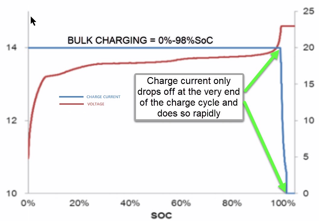
Drop In Lifepo4 Batteries Be An Educated Consumer Marine How To

Simple Local Area Network Lan Berbagisolusi Ethernet Cable Local Area Network Computer Maintenance

Ruger Daily Bulletin
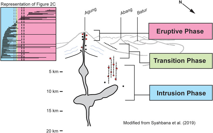
Frontiers Repeating Earthquakes During Multiple Phases Of Unrest And Eruption At Mount Agung Bali Indonesia 2017

Toyota Car Radio Stereo Audio Wiring Diagram Autoradio Connector Wire Installation Schematic Schema Esquema Car Audio Pioneer Car Audio Car Audio Installation
List What You Have Self Hosted R Selfhosted

Block Diagram Of The Proposed Rf Repeater Download Scientific Diagram

What Are Three Way Speaker Crossovers Crossover Networks Briefly Described Using Circuit Schematic Bright Subwoofer Box Design Subwoofer Box Audio Amplifier

Forward Pass Calculation Precedence Diagram Edrawmax Editable Template Diagram Dichotomous Key Construction Activities

Block Diagram Of The Proposed On Channel Repeater With Echo Canceller Download Scientific Diagram
Methods And Practices For Setting Speed Limits An Informational Report Safety Federal Highway Administration

Repeater Basics What Is A 2 Way Radio Repeater And How Is It Used Bridgecom Systems

Block Diagram Of The Nth Receiving Circuit Rx N Download Scientific Diagram
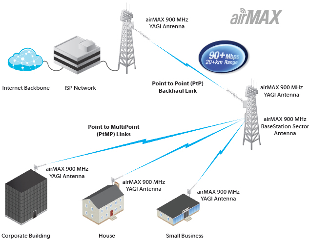
Ubiquiti Airmax Yagi Antenna Netwifiworks Com

Simplified Block Diagram Of An Echo Canceller In An On Channel Repeater Download Scientific Diagram

Proposed Repeater Block Diagram Download Scientific Diagram